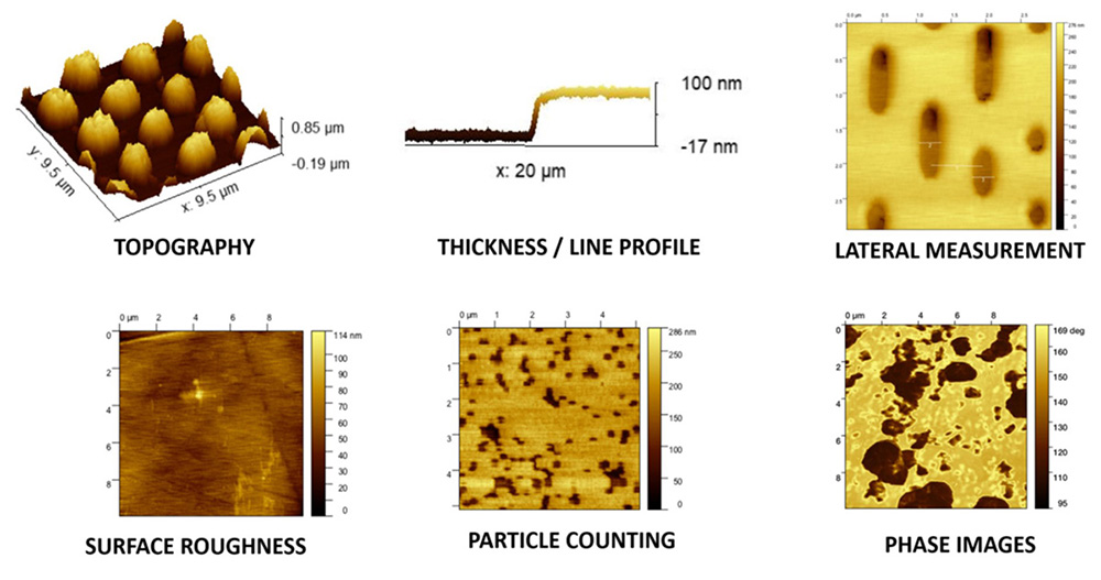
Phase images using ICSPI AFM-on-a-Chip tools
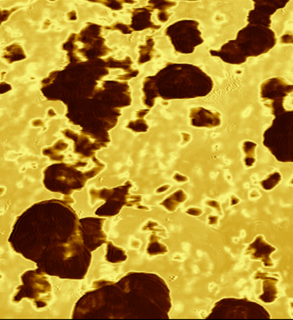
Phase images taken by an AFM. … Phase what?
Typically, an AFM uses a tiny tip or cantilever to scan across the samples surface. The result is often a 3D image of the topography of the corresponding surface.
Especially in the so-called tapping mode of operation (no permanent contact of the tip and the surface) there is an additional information available from the scans which is called Phase image.
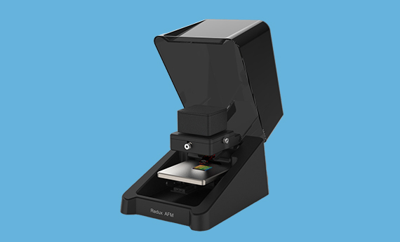
The ICSPI AFM-on-a-Chip tools (nGauge, Redux and Vertex) are working in the tapping mode and provide this Phase image capability or information out of the box … how cool, isn’t it?
Understanding phase images
To understand Phase images, you need to know that in tapping mode the tip is forced to oscillations with a frequency near its resonant frequency. While scanning across the regions of different mechanical properties (hardness, adhesive, stiffness, friction etc.) the interaction of the tip and the surface will cause the oscillation to lag (delay) or in other words giving a phase shift. This phase shift is between the driving signal and the feedback signal from the tip.
Differences in phase images are often attributed to some kind of boundary like material boundary, grain boundary, edges of particles just to mention a few of them.
Phase contrast images can give certain information that might be lost in just a topographic image.
Because there are a lot of different factors affecting the phase, the corresponding information from phase images is often more qualitative rather than quantitative.
Benefits of using
So, using the ICSPI AFM-on-a-Chip tools regions of different mechanical properties can de distinguished by the contrast of the Phase image with very high lateral resolution.
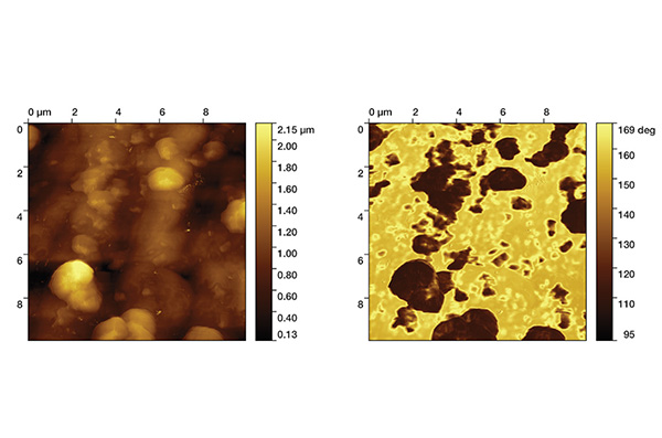
The example below shows the topography image (left) and the corresponding phase image (right) for silica-polymer composite material. The bright areas in topography image show certain particles protruding from the samples surface (the tallest features). The phase image on the right clearly reveals different regions. Light regions (larger phase shift) correspond to the polymer matrix while dark regions indicating silica particles.
Capabilities of the nGauge AFM
